
MICROLIGHT AIRCRAFT OWNERSHIP
Unlike conventional aircraft with their established maintenance schedules and regular inspections by aircraft engineers, microlights in New Zealand rely largely on the owner/operator to take responsibility for maintaining the aircraft's airworthiness, detecting faults and organising correct repair. It is a responsibility not to be taken lightly, but one which the owner/operator can easily manage by ensuring a regular and thorough inspection of the aircraft is made. This is in addition to the normal preflight inspection which the pilot in command is responsible for.
It should be assumed at every inspection that deterioration has taken place. Only by constant vigilance can structural failures be checked. Remember that by nature of their very design, virtually every component of the microlight is vital to the overall airworthiness.
Every Class 2 (2 seat) microlight must have a valid "Permit to Fly " before it can be flown. All microlights must also have a current annual inspedction. Microlight Inspection Authority people are available for this-� contact your local club.
Once the owner/pilot has completed his or her training and gradually leaves the watchful eye of the instructor, there may be a tendency for flying standards to lower. Here again it is the pilot's responsibility to ensure flying skills are maintained. Remember that instructors are available to help.
Indeed skills should continue to grow with experience, and pilots are encouraged to seek qualified advice if ever they feel they need it, in the interests of safety and increased enjoyment of the sport.
WEIGHT AND BALANCE
All aircraft are designed to operate within certain load and balance conditions. It is the pilot's responsibility to make sure that the microlight is not overloaded and is within its centre of gravity limits.
When loading an aircraft there are three kinds of weight we must consider:
- Empty Weight � this is the weight of the basic microlight, the airframe, engine all fixed instruments and equipment, unusable fuel supply, undrainable oil (if any).
- Useful Load or Payload � This is the weight of pilot, passengers, useable fuel supply, baggage and drainable engine oil (if any).
- Gross Weight � (M.A.U.W.) This is the empty weight plus the useful load, giving us the gross weight at takeoff.
When the machine is loaded to the maximum weight stated in the manufacturers manual, the machine is at Maximum All Up Weight (M.A.U.W.).
This is also referred to as Maximum Takeoff Weight (M.T.O.W.).
The manufacturer will normally state in the owner's manual (it's a good idea to placard it in the microlight) the maximum and minimum weight of pilot and passengers. Remember a person's weight includes the weight of clothing and items carried.
What happens if we exceed the weight limits advised?
OVERLOADING
Overloading a microlight will severely reduce the aircraft's performance! It will result in:
- A higher takeoff speed.
- Longer ground run.
- Reduced rate of climb.
- Reduced angle of climb.
- Shorter range.
- Reduced cruise speed.
- Increased stall speed.
- Increased sink rate.
- Higher landing speed.
- Longer landing roll.
- Lower maximum ceiling.
- Decreased g loading capability.
Take another look at this list. If you overload your aircraft you will not suffer from just one of the above, but ALL of the above!
An aircraft with a designed load factor of 3.8g at MAUW,flown with a 25% overload, has its capability reduced to about 3.0g.
Balance
Further to the issue of loading your microlight there is the equally vital question of whether or not the aircraft is balanced correctly.
Centre of Gravity
This is the term used to describe the point about which an aircraft would balance if suspended.
If the aircraft is loaded so that the centre of gravity is within the fore and aft limits prescribed by the manufacturer, then the aircraft will handle and function normally (assuming it is not overloaded!).
Few microlight manufacturers provide aircraft type �loading graphs to help determine the centre of gravity for whatever load it is intended to carry. However, they will normally indicate minimum and maximum pilot/passenger/baggage weights and keeping within these limits assures a correctly balanced aircraft. Consult your owner's manual and study any information therein related to the weight and balance of your aircraft.
Loads forward of the centre of gravity "C of G" (which is usually about 1/3 mean chord) impose a nose down force, and loads aft of the centre of gravity impose a tail down force. Loads at the centre of gravity do not alter the C of G.
The further the distance from the C of G a load is placed, the greater the effect on the balance will be. When the loads ahead and aft of the C of G are proportioned correctly, the aircraft will be balanced for flight.
Effect of Aft C of G
With an aft C of G (too much weight behind the desired C of G) generally an aircraft becomes more pitch unstable and often stall characteristics become more violent. Extra nose down control input will be needed to prevent the aircraft pitching up into a stall. On takeoff the aircraft might develop a high nose attitude which may be difficult or impossible to correct. Only very light control forces will be needed to pitch the nose up, and in this condition the aircraft may easily be overstressed.
Effect of Forward C of G
With the aircraft loaded with a forward C of G (too much weight ahead of the desired C of G) extra nose up control input will be needed to prevent the aircraft pitching down. There may be insufficient nose up control available to rotate for lift�off and for flaring for landing. Dive recovery will be impaired.
Both the previous conditions cause pilot fatigue as the unusual loads required on the controls may be more than the aircraft's trim systems can relieve (assuming it has one). Weight and balance must be taken seriously.
"A Microlights behaviour in the air is dependent on weight and balance"
THE PROPELLER
The job of the propeller is to convert engine power into forward thrust. The propeller is made to rotate by the engine, and in doing so develops lift at approximately right angles to the plane of rotation. This produces a backward stream of air called the slipstream, which is the thrust.

Fig. 53 The action of the propeller through the air is similar to that of a wood screw through wood.
The aerofoil section of each propeller blade is set at an angle to the plane of rotation, this is called the Pitch.
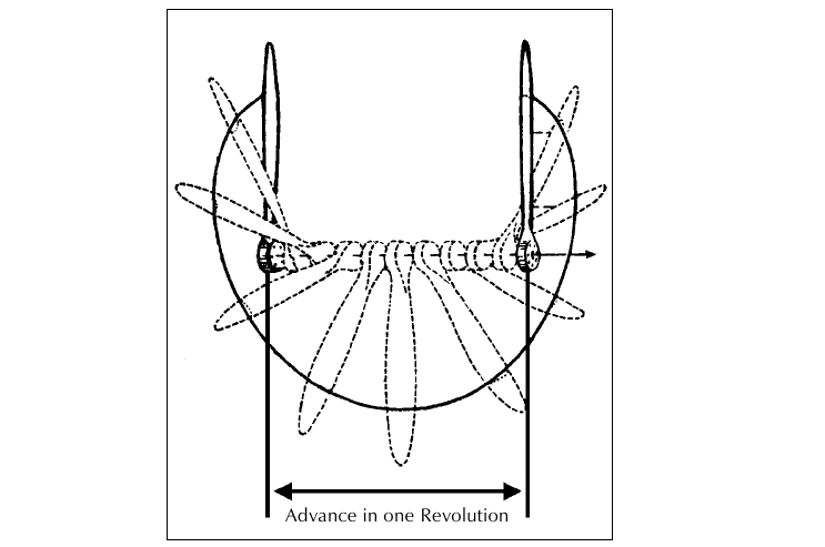
Fig. 54 Because the tips of the propeller travel very much faster than near the hub, the pitch is at its maximum at the hub and progressively reduces towards the tips.
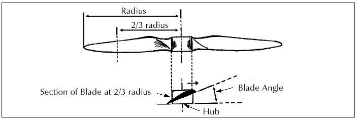
Fig. 55 Propeller theory is complicated by the fact that the propeller blade angle relative to the airflow changes with forward speed and R.P.M., being at its maximum while the aircraft is at rest at high R.P.M., reduces to a minimum during flight at maximum speed, and assumes a negative angle in a steep dive at low R.P.M. In this respect the fixed pitch prop will only be at its most efficient at the revolutions and forward speed intended by its designer.
This last point highlights the dilemma of the fixed pitch propeller. A fixed pitch propeller can be designed to be most efficient at only one task, e.g. a fast cruise speed. While it may excel at one task, it may be fairly unsuited to another. For this reason most fixed pitch propellers are designed as somewhat of a compromise to provide adequate performance for each task, although probably favouring one goal.
Two such propellers are the Cruise and Climb propellers. A propeller designer wishing to produce a propeller that will afford a fast cruise speed will create a coarse pitch design. The coarse pitch refers to a larger blade angle which will produce good thrust at lower R.P.M. and at a greater forward speed. However, this propeller will result in an extended takeoff run and reduced climb performance.
| Cruise propeller | Advantages | Disadvantages |
| Coarse pitch | Good cruise speed | Long takeoff roll |
| Poor climb performance |
| Climb propeller | Advantages | Disadvantages |
| Fine pitch | Good takeoff run | Low cruise speed |
| Good climb performance |
A propeller designed to give a short takeoff and good climb capability will be of a fine pitch design. The fine pitch refers to a lesser blade angle, which will produce good thrust at high R.P.M. (takeoff power) and low forward speed. Thus an aircraft with a fine pitch prop will accelerate quickly, takeoff with a shorter ground run and climb well . Unfortunately the cruise speed will not be as good as with a cruise prop.
Propellers are described in terms of their diameter and pitch. For example a 54x27 inch prop is a propeller 54 inches in diameter, and with a theoretical pitch giving 27 inches of forward movement per prop revolution.
The long distance flyer will probably choose a cruise prop for his/her aircraft, while the pilot who does not fly far, but sometimes operates from smaller fields, would require a climb propeller.
Of course, a variable pitch prop, adjustable in the air, would provide the best possible solution, enabling the use of fine pitch for takeoff and climb and then coarse pitch for cruise. Unfortunately such propellers are not commonly in use on microlights and are sure to be expensive and significantly heavier.
There are available however, ground adjustable units. The idea here is that the pilot can select and set up the desired pitch before takeoff according to the task at hand.
Propeller Care
When you start the engine and the propeller becomes a blur, it is easy to overlook the incredible forces it is coping with during the course of its work. As it spins centrifugal force tries to rip each blade out of the hub. At the same time there are various twisting and bending forces associated with the production of thrust. At high R.P.M. in particular the propeller is under enormous strain.
When we consider that the propeller is also acting as a flywheel, it is plain that it must be perfectly balanced in order to spin smoothly without vibration. With the high tip speeds any imbalance will cause serious vibration. Furthermore like any lifting surface it must be aerodynamically balanced to operate smoothly.
Microlight propellers seem to suffer from more than their fair share of woes. They are mainly constructed from carbon fibre or from laminated wood and although this material is well suited to the task, the prop needs a fair amount of care during its life.
A propeller's (especially wooden) biggest enemies are the likes of water, stones, sticks, thistle stalks, cow pats, sheep manure and mother earth.
The outer third leading edge of each blade is the most subject to damage from these things, and normally this section is given some sort of protection in the form of a plastic tape, fibreglass coating, metal cap or other. These devices are intended to help reduce impact damage (small objects only) and abrasion to the leading edge. Flying in rain, a wooden prop without leading edge protection can be badly damaged as the raindrops blast through the varnish and begin tearing at the wood fibres, thus in a short time the leading edge may be ruined.
Obviously, a stone or other hard object striking the prop will really do some damage. Stones and gravel usually find their way into the prop disk by being sucked up off the ground by the propeller if it is near enough, or by being thrown up by the wheels. It pays to assess an airfield's surface carefully, even pace it out, to check for anything likely to cause propeller damage. That discarded piece of fencing wire lurking in the grass could spoil your day.
The propeller itself deserves special attention during the preflight. Inspect both faces of each blade and each edge, looking for nicks, worn spots, cracks. Wipe the prop clean if needed. Check the security of any leading edge protector. A piece of propeller tape for example, missing or peeling off, could produce vibration bad enough in flight to necessitate the immediate shut down of the engine! Watch for play around the propeller hub mounting. Any damage should be considered serious and replaced or repaired by someone qualified.
If vibration occurs in flight suspect propeller trouble, reduce power if possible and land. In the event of severe vibration � shut the engine off immediately. Treat all propellers as live and never allow people near your aircraft while the engine is running.
Reduction Drives
The use of small two�-stroke engines in microlights has necessitated the use of reduction drive because these engines develop their power at R.P.M. far in excess of suitable propeller R.P.M.
To give an example, a small propeller of say 48 inches diameter would have a tip speed of 785 M.P.H. (685 kts) when driven at 5500 R.P.M. assuming the engine could develop sufficient power. Much of this power would be wasted shock waves as the propeller exceeded the speed of sound across the outer areas of the blade. Therefore, some sort of reduction is needed to match ideal propeller speeds with the best engine efficiency R.P.M.
These can take the form of:
- Chain drive.
- Toothed belt drive.
- Multiple V belt drive.
- Gearbox.
The most commonly used reduction method utilises a gearbox with a reduction of approximately 2.5 to 1, i.e. the engine runs at two and a half times the propeller R.P.M. Gearboxes require the oil to be checked regularly.
If a belt reduction is used the belts must be checked during preflight for correct tension and wear.
The correct tension is maintained with an adjusting device. Slipping belts result in a loss of power to the propeller, and rapid and destructive wear to the belts. A good feature of belt drives is their ability to absorb engine and prop vibrations. Accurate alignment of pulleys is important.
PISTON ENGINES
The microlight engine produces power by converting petrol into heat and energy. The energy is collected by mechanical means and the resultant power is transmitted by a rotating shaft which is linked to a propeller in the aeroplane. It is self evident that when ignited a liquid fuel will burn and produce heat but how the heat is able to provide mechanical energy will be less obvious until it is realised that heat can be applied to air. When heated, air will expand considerably, exerting great pressures if contained in any way.
Method
To provide perfect combustion in the engine, petrol and air must be mixed in a ratio of approximately fifteen parts of air to one part of petrol by weight. Too much petrol causes a "rich" mixture (which may be recognised by black exhaust smoke). This is both wasteful of fuel and damaging to the engine because heavy carbon deposits build up in the combustion areas.
Conversely, too little petrol in relation to air causes a "weak" mixture. This too, is damaging to the engine, for instead of the mixture burning at an even rate on ignition, an explosion occurs causing severe strain on the engine accompanied by overheating and loss of power. In most piston engines fuel is mixed with air in the "carburettor".
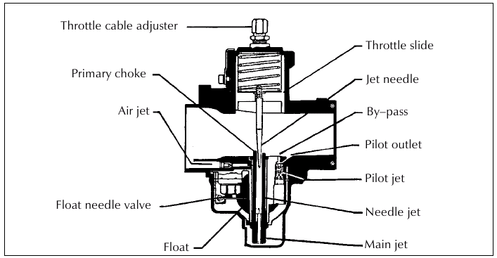
Fig. 56 Cross�Section of a float carburettor.
Fuel from the aircraft tanks is pumped to the carburettor and enters a device similar in design to a domestic toilet cistern called a "float chamber", its function being to maintain the fuel at the correct level in the "jets". These jets create an atomising action rather similar to that of the nozzle of a scent spray. It is usual to provide a "slow running jet" for the purpose of engine idling and a "main jet" for normal operation. On some carburettors when the throttle is opened for maximum power an additional "power jet" is brought into operation.
A reduction in air density will occur as the aircraft gains altitude and since this would result in an over rich fuel/air mixture, the carburettor may be provided with a "mixture control". A throttle slide is positioned between the jets and the engine and linked to the pilot's throttle control so that the amount of mixture entering the engine may be regulated, this in turn determines the power output to the propeller.
The carburettor just described is typical of the type used in many microlights powered by simple two-�stroke engines. Some microlight motors are fitted with a diaphragm carburettor (instead of a float chamber type). The advantage of these carburettors is that they are not affected by operating in any attitude.
The tuning of any carburettor is important and should be done in accordance with your particular engine manual. For two-strokes, because they can generate large amounts of heat quickly, correct tuning is critical. A useful check for correct tuning is to examine the spark plugs after a full power run, they should look a light tan in colour. If they are blackish then your engine is too rich. If they are whitish then your engine is too lean.
For engines with dual carburettors it is important that the throttle slides are set the same throughout the throttle range. The jetting and float levels must also be the same.
Provision of Rotary Motion
In a bicycle the reciprocating motion of the rider's legs is transmitted to the crank via a pair of pedals so converting an up and down motion into a rotation which is transmitted by a chain to the rear wheel.
In a piston engine the crank and pedals are replaced by a "crankshaft" and the "legs" of the engine are provided by a "connecting rod" which links the crankshaft to the piston (the muscles of the leg). To allow for the sweeping motion of the crankshaft as it rotates within its "crankcase" provision is made for the connecting rod to pivot on a "gudgeon pin" inserted across the piston axis which passes through the "small end" of the connecting rod and the "crank pin" (equivalent to the pedals on a bicycle) is free to rotate in the connecting rod "big end bearing".
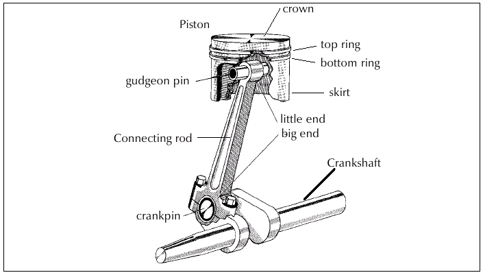
Fig. 57
When the engine is running at 3000 R.P.M. the piston and connecting rod must go up the cylinder, stop, descend down the cylinder and stop again (ready for the next ascent), fifty times every second, and it is usual practise to counterbalance the crankshaft so that vibration is kept to a minimum.
Cooling
Quite apart from the heat generated by fast moving parts is the very considerable heat resulting from combustion in the mixture. When running at 3000 R.P.M. an engine such as the single �cylinder unit under discussion would ignite every revolution or at 3000 R.P.M., 50 times per second. When there is a need to burn more fuel to provide extra power (e.g. during a climb) the engine temperature increases. Unless the surplus heat generated were dissipated in some way it would only be a matter of minutes before the cylinder head became excessively hot and the engine seized. In a car the problem is solved by surrounding the cylinder and cylinder head with a series of passages cast in the cylinder block. Water is pumped through these passages (water jacket) and returned through a radiator to disperse the heat by the air flowing through it.
While liquid cooling has in the past been adopted for some very successful high performance aero engines (notably the Rolls �Royce Merlin) large engines are now practically confined to the gas turbine family. Lower power aero engines have almost without exception always relied upon a cooling system which dispenses with the radiator and its tank, the water jacket around the cylinder and the coolant itself. This simpler and lighter method, in fact the one used on motor cycles and small petrol mowers, is called "air cooling". Fins are machined around the outside of the cylinder barrel and cylinder head and a system of sheet metal baffles guides the airflow through the engine cowling and around the fins, carrying away the excess heat through the rear of the engine bay.
Liquid cooling is now more common in microlights, due to technological advances. Unfortunately some two �thirds of the fuel energy in an internal combustion engine is wasted, only the remaining third being converted to power.
The Two�Stroke Engine
Although four�-stroke power units are available, the two�-stroke engine is still the most commonly used for microlight aircraft, primarily due to their relatively lower cost and higher power to weight ratio. The two-�stroke engine is less fuel efficient than the four- stroke per horsepower, although it generates more heat, it also has less tolerance to running lean etc. The two-�stroke engine has fewer moving parts than a four-stroke because it does not have complex valve train components.
Feeding the Mixture to the Engine
The need to draw in and compress the mixture, burn it then clear the cylinder (making it ready to accept another charge) is essential to all piston engines, but in a two-�stroke design two functions are enacted simultaneously.
It will be seen (in Fig. 58) that no mechanical valve gear is provided. Instead the piston is arranged to cover and uncover ports cut into the cylinder walls thus providing the dual function of compressor/power collector and inlet/exhaust valves.
Imagine the engine is running. As the piston rises to compress a fresh charge, pressure decreases within the crankcase, the inlet port is uncovered by the piston skirt and mixture from the carburettor flows in. The engine fires and during the power stroke the inlet port is closed, and the mixture trapped within the crankcase is compressed by the descending piston. Towards the bottom of the power stroke the piston crown uncovers an exhaust port and at the same time opens a transfer port which communicates between the crankcase and the top of the cylinder (i.e. combustion chamber).
Mixture under pressure within the crankcase now escapes through the transfer port to the combustion chamber. The incoming mixture assists exit of the burned gas through the exhaust port.
Note the design of the piston crown which is contoured to encourage the gas flow just described.
During the next compression stroke a fresh charge of mixture will be drawn into the crankcase ready for transfer to the combustion chamber as the following stroke occurs.
In some higher performance two-stroke engines the inlet port is controlled by either a rotary disk valve or a reed valve. These valves give more control over fuel/air mixture intake timing and result in a greater charge being drawn in each cycle, and hence greater power.
Having regard to the fact that a two-�stroke engine produces a power stroke every revolution, one might expect it to develop twice the power of a four�-stroke engine of similar capacity.
Spark plug
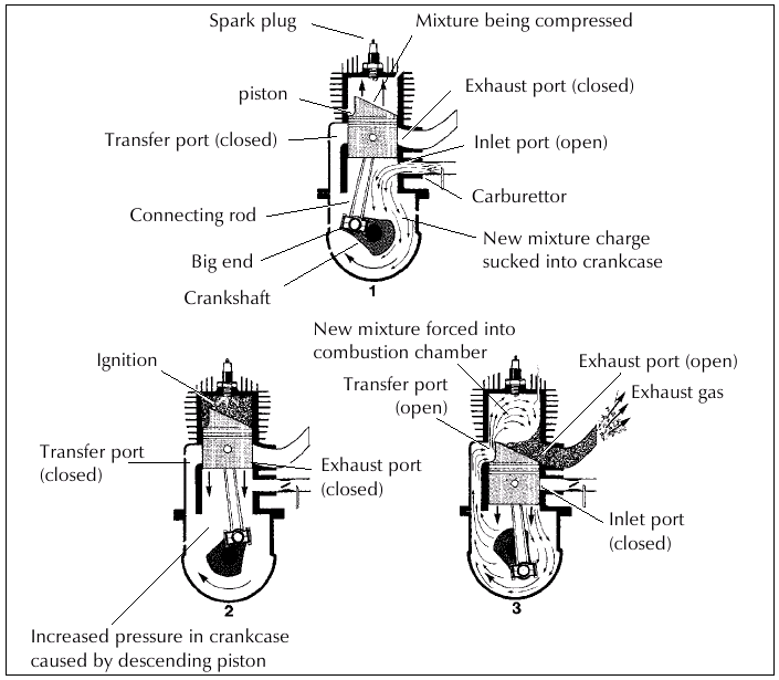
Fig. 58 Typical two stroke engine.
Unfortunately scavenging of the exhaust gas and imperfect induction reduce its efficiency and, on average, a two�-stroke will develop only 50 per cent more power than a four�-stroke engine of the same capacity. Furthermore, both oil and fuel consumption per horsepower hour is higher for a two-�stroke. Against this must beset the advantages of simplicity and low weight per horsepower.
Air Filters
There are only two inputs that are mixed to cause the engine to develop power � Petrol and Air.
The Air Filter is an important component that requires regular attention. Regular cleaning of the Air Filter will ensure that the engine does not start to run "rich". If the two�stroke engine is caused to run "rich" then a consequence can be that it will "bog down" as the power is applied. This event can be disastrous on final approach. Typically the Air cleaner and the spark plugs are attended to at the same time.
Lubrication
Unlike the four�stroke engine with its wet sump or separate oil tank, oilways, and, in many engines, oil pump(s), two-strokes are lubricated by the simple method of mixing suitable oil with the petrol. When one of the modern oils developed for two�-strokes is used the normal mixture is one part to 50 parts of petrol. However this may vary in engine brands, so always consult the manufacturers handbook or aircraft flight manual for the type of oil recommended and amount to be used.
Excessive use of oil will lead to heavy carbon deposits around the exhaust ports and fouled sparking plugs. The petrol and oil mixture (often called petroil) must be thoroughly shaken to ensure even distribution of the oil before refuelling.
Some higher performance two-stroke engines use oil injection, where a metered amount of oil from a separate reservoir is injected into the crankcase inlet on each cycle. This eliminates the need for premixed fuel and oil.
Cooling
In addition to the cooling fins already described in the earlier section, some two�-strokes have a small cooling fan attached to the drive shaft. Water� cooled engines are also common in higher powered two-stroke engines. These utilise a "water jacket" built into the engine block and head, through which coolant (usual y a 50/50 mix of water and antifreeze) is pumped. Having absorbed heat from the engine, the coolant is then piped to the radiator (usually mounted in the airflow but where it will cause the least amount of drag) which disperses the heat into the surrounding air, thence back to the engine to reabsorb more heat.
Care of water cooling components is relatively simple:
- Check the coolant level before each flight.
- Check hoses and the radiator for leaks or damage.
- Check all mounting hardware for security.
Ignition
Purpose �built four-�stroke aero engines and some newer two-stroke engines are provided with two independent ignition systems (dual ignition) to:
- ensure safety, and
- provide better ignition of the mixture in what is by automobile standards a large volume combustion chamber.
Microlight engines now have both single plug and dual plug ignition systems, with either solid state, electronic or magneto type ignition.
The spark plugs on either type of engine require regular maintenance. Cleaning or replacing and regapping at 25 hours is a fairly typical recommendation.
Engine Handling
Be sure to follow any engine operating procedures recommended by the engine manufacturer.
Proper handling will improve the reliability of an engine greatly.
Some points to remember:
- use of continuous high R.P.M. settings will cause increased strain and wear of components; this may lead to high cylinder head temperatures which in turn can cause detonation and poor cylinder wall lubrication.
- do not use high power settings until the engine has warmed. High R.P.M. causes very rapid wear to a cold engine. Therefore, takeoff must be delayed until cylinder head temperatures are above the minimum.
- the throttle should be advanced smoothly to prevent strain on the engine.
- the fuel mixture and carburettor mixture must be kept at the recommended settings.
- avoid long power�off descents which can lead to a spark plug fouling � warm the engine periodically.
- remember that at high power and low airspeed (climb), engine cooling will be diminished.
- constantly monitor engine temperatures in flight.
- use full throttle to ensure a richer mixture to reduce overheating and improve lubrication during climbout
- avoid rapid application of full power after a prolonged descent to avoid 'cold seizure'. Warm the engine periodically during descent, and apply power smoothly after descent.
"If you want a reliable engine, look after it!!"
Fuel Storage
Not surprisingly, petrol engines perform well on petrol and not at all on water and other contamination. Ensuring your engine always has a good supply of clean fuel goes a long way toward preventing engine failures. Containers used for fuel storage should be completely clean and without residue of anything else they may have contained. There should be no sediment or deterioration of the inside surfaces. Likewise the associated hoses, funnels and pumps used must also be clean.
Water can mysteriously find its way into seemingly leak-proof containers and microlight fuel tanks by means of the condensation process. To minimise this, keep fuel containers as full as possible.
Fuel drums should be stored on their sides if in the open, so that the expansion and subsequent contraction of the fuel and drum cannot draw in water which has collected in the rim.
On the first preflight of the day and after every refuelling, include a check for water which will collect in the low points of the system, this can best be removed by a drain tap at that point. Drain a little fuel into a glass and water will appear as bubbles on the bottom.
Mixing the correct ratio of the right oil to petrol for two�-stroke engines is vital! It may be helpful to draw up a chart showing the appropriate amount of oil for various amounts of petrol. Be particularly careful when mixing fuel in the microlight's fuel tank on an out landing or cross�-country stop. Know what you are doing! Your engine manual will specify what octane rating your engine requires.
Only use fresh fuel as it deteriorates with time. Old fuel has a reduced octane rating which may cause engine problems.
Fuel Management
Fuel related accidents usually fall into three categories � Fuel contamination, Fuel starvation and Fuel exhaustion. Fuel contamination is covered above. Fuel starvation and exhaustion are the result of poor pilot practise.
Fuel Exhaustion
Is simply running out of fuel. That's it, you've burned every last drop, meaning an engine failure and forced landing. Knowing what sort of endurance you have, plan your flight to have at least 20 minutes of fuel remaining, once the flight is completed. Do not be tempted to reduce this safety margin. There are many reasons for keeping this reserve of fuel such as the situations below, which all eat into your fuel supply:
- unexpected headwinds.
- use of high power settings longer than usual as in multiple takeoffs or climbs to altitude.
- becoming lost.
- the need to divert to another destination due to weather, wind or unserviceability of proposed landing field etc.
- higher than normal fuel flow. Whenever possible take off with a full fuel load. Be thoroughly familiar with your aircraft's fuel capacity and know what sort of endurance you can safely expect at the power settings you use, for the amount of fuel you are carrying.
If you find yourself in a situation where there is doubt that the fuel remaining is going to be sufficient to reach a destination safely, then don't press on, land at the next safe field.
It is far safer to make a precautionary landing with power than an emergency landing without power where landing options are severely limited.
"I think I can make it" is right at the top of the list of famous last words in aviation history.
Remember � the useable capacity is not necessarily the total capacity of fuel carried due to the location of the fuel pick up point.
Fuel Starvation
This can occur in microlights with fuel on/off taps and/or more than one fuel tank, where the fuel supply is interrupted by wrongly positioning the fuel tap. It may sound unlikely that anyone would select the fuel off or change to an empty or near empty tank, but it certainly happens.
The obvious cure for fuel starvation problems is to stay aware of your fuel system. The fuel selector would normally be positioned "on" to the appropriate tank before start up and checked again before takeoff during the pre�takeoff checks.
The fuel filter/drain should be checked for contaminants/water, prior to flight.
In flight the pilot should constantly monitor the fuel situation and know beforehand when the change to another tank should be made. Needless to say, don't wait until the "Big Silence" before changing to the new tank either!
Ensure fuel selectors are clearly marked as to their positions and when moving the selector think about your action. Don't rush your preflight checks.
Summary �
- Know your fuel system � selectors, on/off valves etc.
- Know the useable capacity of fuel on board.
- Know the consumption rates at various power settings for the particular microlight being flown.
- Check for fuel contamination after every refuel.
- Don't change tanks just before takeoff- � allow time to verify the fuel flow before takeoff.
- Always check fuel quantity yourself before flight.
- Plan to have easily enough fuel plus reserve for each flight.
- Keep refuelling equipment clean.
- Constantly monitor fuel state in flight.