
Forces acting on the microlight
A microlight in flight has four forces acting upon it.
WEIGHT, LIFT, THRUST, DRAG
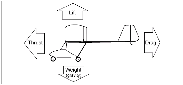
Fig. 2 The four forces acting on an aircraft in flight.
- Weight: Acts vertically down (gravity) and has to be overcome by a force acting vertically upwards so that flight may be sustained. It is basically constant in flight except for a decrease taking place with the usage of fuel.
- Lift: Acts upward to overcome weight. It will vary according to airspeed and/or angle of attack. It acts at right angles to the airflow but not necessarily in exact opposition to weight when out of level flight.
- Thrust: Produces the forward movement which provides an airflow over the wing. It will vary according to the power applied and/or the angle of attack.
- Drag: The force which tends to hold back or resist forward movement. Drag varies with airspeed and angle of attack and acts in opposition to thrust.
During straight and level flight at a constant speed LIFT equals WEIGHT, THRUST equals DRAG, and the aircraft is said to be in equilibrium.
Any inequality between lift and weight will result in the microlight entering a climb or descent. Any inequality between thrust and drag will result in acceleration or deceleration. Before discussing these four forces further, let us examine some of the terms used extensively in this section.
Airfoils
An airfoil is a device which gets a useful reaction from air moving over its surface. When moved through the air it is capable of producing lift. Wings and propellers, horizontal and vertical tail surfaces are all examples of airfoils. For convenience we will use a crosssectional view of a wing in our discussion. Microlights can have either a single surface or a double surface wing as drawn in crosssection following. However, for our purposes we will use a double surface airfoil. See Figure 3.
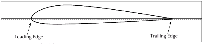
Fig. 3 Cross-section of a typical airfoil with chord line.
The forward part of an airfoil is rounded and is called the leading edge. The aft part is narrow and tapered and is called the trailing edge. A reference line often used when discussing airfoils is the chord line. The chord line is an imaginary straight line joining the tips of the leading edge and the trailing edge.
Angle of Incidence
The angle of incidence (see Figure 4) is the angle formed by the chord line and the longitudinal axis of the microlight. The longitudinal axis being an imaginary line running lengthways through the machine from nose to tail. The angle of incidence is not usually able to be changed by the pilot.
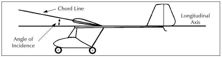
Fig. 4 Angle of Incidence.
Relative Wind
The relative wind is the direction of airflow in relation to the wing. If, for example, a wing is moving forward horizontally, the relative wind moves backwards horizontally. If a wing is moving forward and upward, the relative wind moves rearward and downward. Thus the flight path and relative wind are always parallel, but travel in opposite directions. See Fig. 5. A microlight moving through the air has relative wind, just as does a microlight stationary on the ground with the wind blowing over it.
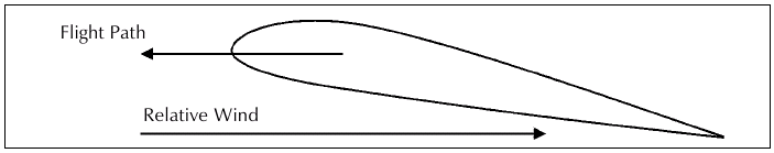
Fig. 5
Angle of Attack
The angle of attack is the angle between the direction of the relative wind and the chord line of the wing, (or between the flight path and the chord line). See Fig. 6. Do not confuse angle of attack with the angle of incidence. The angle of incidence is normally fixed, but the angle of attack may be varied by the pilot and is relative to the flight path.
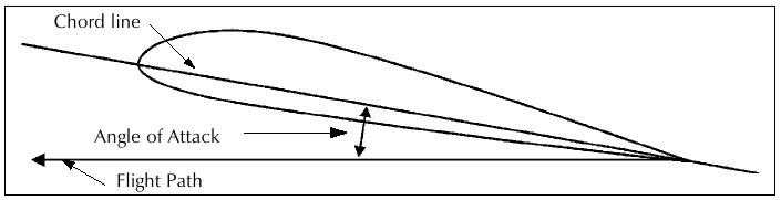
Fig. 6
Bernoulli's Principle
Many years ago the scientist Bernoulli discovered that the pressure of a fluid (liquid or gas) decreases at points where the speed of the fluid increases. This simply means that highspeed flow is associated with low pressure and low speed flow is associated with high pressure This principle has particular application to airfoils, which are designed to increase the velocity of the airflow above their surfaces. This decreases the pressure above the airfoil. At the same time, the impact of air on the lower surface of the airfoil increases the pressure below. It is this combination of decreased pressure above and increased pressure below which produce lift. Approximately 80% of lift is produced by the TOP surface. See Figs. 7 & 7a.
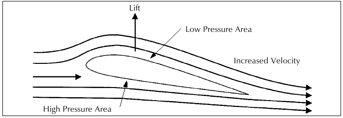
Fig. 7

Fig. 7a Lift distribution Upper and Lower surfaces .
Lift
We have already mentioned that it is the airflow over the airfoil which produces the lift. The upward component of this force is lift, but during its production there is a rearward component and this is induced drag. See Fig. 8.
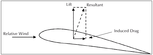
Fig. 8
Drag
The total drag of a microlight, as shown on the four forces, is actually made up of two types of drag: Profile or Parasite Drag and Induced Drag.
Profile Drag is simply the drag created by the form itself of the microlight airframe, undercarriage, rigging, etc. As the speed increases, profile drag increases sharply. In fact, if the speed is doubled the drag is four times as much as for the previous speed.
Induced Drag is a result of the production of lift by the wings/airfoils. At high angles of attack the induced drag is high. At low angles of attack the induced drag is low. The use of streamlining of the airframe results in significant reductions in parasite drag, but reduction of induced drag is more difficult.
Briefly, long slender wings (high aspect ratio) such as found on sailplanes minimise induced drag. Wide chord wings of short span (low aspect ratio) produce more induced drag. See Figure 9.
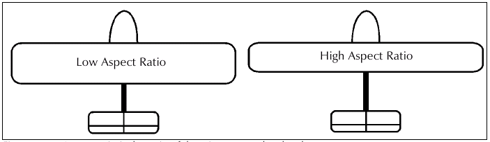
Fig. 9 Aspect ratio is the ratio of the wingspan to the chord.
Relationship between Lift and Angle of Attack
As mentioned before, the angle of attack is the acute angle made by the chord line of the wing and relative wind or flight path. At small angles of attack there is a small differential between the increased pressure beneath the wing and the decreased pressure above the wing.
By increasing the angle of attack, the effective camber (curvature) of the wing is increased. Thus the air is required to travel a greater distance in the same time. In order to travel this greater distance, Bernoulli's Principle tells us it must accelerate, producing a greater decrease in pressure. So, increasing the angle of attack results in an increased pressure differential, meaning greater lift. It also results in increased induced drag. See Figs. 10a &10b.
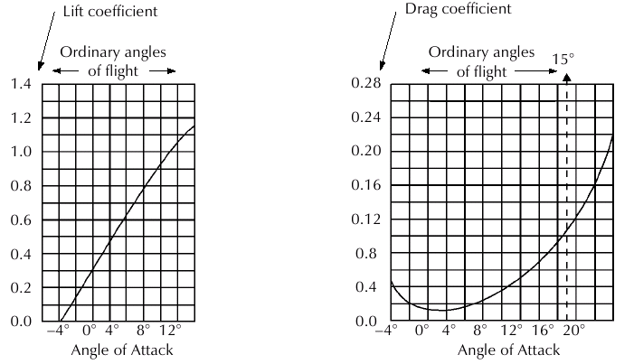
Fig. 10a Lift Curve. Fig. 10b Total Drag Curve.
With the angle of attack increased to around 15 to 16 degrees or so on most airfoils, the air can no longer flow smoothly over the upper surface of the wing because a large change of direction is needed. With the increasing angle of attack, and deceleration of the flow against the pressure gradient from low pressure above the wing back to normal pressure at the trailing edge of the wing, break up of the airflow begins at the trailing edge and moves forward. See Fig. 11.
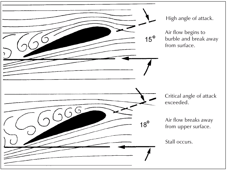
Fig. 11 Ordinary angles
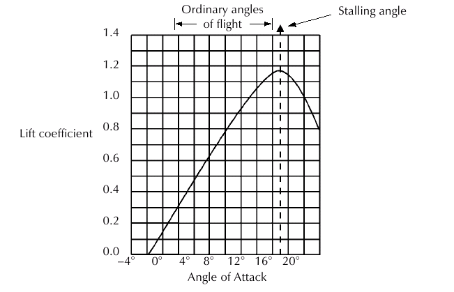
Fig. 12 Lift Curve.
At the critical angle of attack (usually around 18 degrees) the turbulent flow, which has appeared at the trailing edge at lower angles of attack, progressively spreads forward over the whole surface of the wing. This action of the airflow increases the pressure on the top surface of the wing, along with an equally sudden increase in drag. Lift is greatly reduced and the wing is said to have stalled. See Fig. 12. (Refer to Stalling section.)
Should be a diagram and narrative describing both induced and profile drag, and total drag. Spped at which total drag is at a minimum is normally best L/D.
Centre of Pressure
If the pressure forces over the wing were combined to give a single resultant force, then the point where this resultant intersected the chord line would be called the centre of pressure. Since the distribution of the lift forces varies, then it follows that the centre of pressure moves back and forth along the chord with changes in angle of attack. For normal flight conditions the centre of pressure moves forward with increase in angle of attack and rearward with decrease in angle of attack. As the stall takes place the centre of pressure moves rapidly backwards, resulting in the nose of the aircraft pitching down because the new centre of pressure is now aft of the centre of gravity. need a figure to show this
Relationship of Thrust and Drag in Straight and Level Flight
- In straight and level flight at a constant airspeed, thrust and drag are equal.
- If the thrust output of the propeller is increased, thrust will momentarily exceed drag and airspeed will begin to increase (assuming that straight and level is maintained). The increase in speed will cause an increase in drag and at some new higher speed drag and thrust will again equalise. The speed will again be constant.
- At full power, the speed will increase until drag equals thrust and the constant speed this gives will be the top speed for the aircraft in that configuration and density altitude.
- If thrust is reduced to less than the drag, the microlight will decelerate to a slower airspeed (assuming straight and level maintained) where the thrust and drag become equal. Of course, reducing the airspeed too much would result in a stall. As already mentioned, an increase in speed will increase the drag rapidly.
Relationship of Lift and Weight in Straight and Level Flight
The upward force of lift on the wing always acts perpendicular to the direction of the relative wind. In straight and level flight, lift opposes the microlight's total weight. With lift equal to weight, the aircraft will neither climb nor descend. Should lift become more than weight, the aircraft will enter a climb; and if lift become less than weight, the aircraft will enter a descent.
FACTORS AFFECTING LIFT AND DRAG
Many factors alter lift and drag, such as airfoil shape, airspeed over the wing, angle of attack, wing area and air density.
Effect of Airfoil Shape on Lift and Drag
By increasing the upper curvature of the airfoil (up to a point) the lift produced will be increased. Thus, a wing designed for high lift will have a deep wing section and possibly a concave lower surface. High lift wings, by the way, are not suited to highspeed flight because of increased profile drag.
Lowering an aileron has the effect of increasing the curvature of the wing, thus increasing the lift on that portion of the wing. Unfortunately, this also results in an increase in drag creating adverse yaw.
Raising an aileron effectively reduces the camber of that part of the wing, reducing the lift there. It also decreases drag and any adverse yaw.
Moving the tail surfaces also changes their curvature, causing the direction of their lift to change.
Any damage to the contour of the wing will have a serious effect on the lift production of that part of the wing. Stall characteristics may also change for the worse. So don't, for example, fly with sail battens damaged or missing! The shape of the airfoil is critical.
Effect of Wing Area on Lift and Drag
If wing area is doubled, other things being equal, the lift and drag created by the wing will also be doubled. Wing area cannot normally be changed by the pilot.
Effect of Airspeed on Lift and Drag
Increasing the speed of the air passing over the wing increases the lift and drag. This is because of the increased relative wind on the lower surface producing greater positive pressure, as well as the increased speed of the relative wind over the upper surface giving a lower pressure there. If we double the speed, the lift and drag quadruple (assuming the angle of attack remains the same).
Effect of Angle of Attack on Lift and Drag
As already mentioned, increasing the angle of attack increases both the lift and drag, up to a point called the "stall".
Atmospheric Effects on Lift and Drag
The density of the air affects lift and drag. As air density increases, both lift and drag increase and as air density decreases, lift and drag also decrease. The density of the air is governed by Temperature, Humidity and Pressure.
- Pressure An increase in altitude brings a decrease in pressure, which translates to less dense air. Therefore, in order to produce the same lift at altitude, the airspeed over the wings or the angle of attack must be increased. Taking off from airfields at higher altitudes requires longer takeoff distances.
- Warm air is less dense than cool air, therefore performance suffers in warmer air.
- Moist air is less dense than dry air, therefore performance will suffer in moist air.
From above it is clear that on hot, humid days, operating from high altitude fields will see the microlight's performance at its worst
EFFECT OF CONTROLS
Conventional aircraft are considered to have three axes of movement. Whenever the aircraft changes attitude in flight, it will rotate around one or more of these axis. The three axis intersect at the centre of gravity and each one is at right angles to the other two. See Fig. 13.
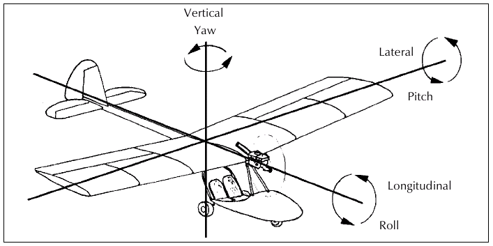
Fig. 13
Three Axis of Motion.
- The Lateral or Pitch Axis: This is a straight line through the centre of gravity and running spanwise toward the wingtips, at right angles to the longitudinal and vertical axes. Movement around this axis is called pitching and is achieved with the elevators.
- The Longitudinal Axis: This is a straight line running lengthways through the aircraft's centre of gravity from nose to tail. Movement around this axis is called rolling and is achieved with the ailerons.
- The Vertical or Normal Axis: This is a straight line through the centre of gravity and is vertical when the aircraft is in the rigging position, it is at right angles to the longitudinal axis. Movement around this axis is called yawing and is achieved with the rudder.
Control Surfaces
For the purposes of this section we will be dealing with a microlight of conventional layout and control configuration. In a later section we will look at some other configurations.
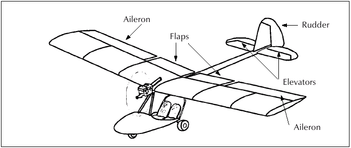
Fig. 14
Controls on a conventional three axis microlight.
- Elevators: The elevators control movement about the lateral axis, which is called pitch. The elevators are hinged to allow the surface to move up and down. On some aircraft, the entire horizontal tail surface may move, but usual y it is only the aft portion that moves. The horizontal tail surface along with the elevators make up a single airfoil. Changing the position of the elevators therefore alters the camber of the horizontal tail surface and thus increases or decreases the lift it produces. The elevators are connected to the control stick and fore and aft movement of the stick moves the elevator surface. Moving the stick forward moves the elevator down, while aft stick moves the elevator up. Forward stick therefore increases the lift of the tail surface and causes the nose to pitch down. The elevators control the angle of attack of the wings. When the nose is lowered, the angle of attack is reduced. When the nose is raised, the angle of attack is increased. See Fig. 15.
The elevators primarily control the airspeed.
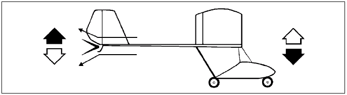
Fig. 15 Effect of Elevator.
- Ailerons: The two ailerons, located at the trailing edge of the wing, are moveable surfaces that control movement about the longitudinal axis. On some types these surfaces span the entire trailing edge of both wings. As one aileron surface is lowered, the other is coupled so that it is raised. The wing with the raised aileron goes down because of decreased lift. Moving the control stick to the right moves the left aileron down and the right aileron up, rolling the microlight to the right. This happens because the down going left aileron increases the wing curvature (camber) and thus increases the angle of attack. The right aileron moves upward and decreases the camber, resulting in a reduced angle of attack. Thus the decreased lift on the right wing and the increased lift on the left wing causes a roll and bank to the right. See Fig. 16.
The ailerons control angle of bank.
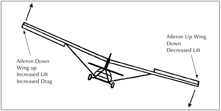
Fig. 16 Effect of right control stick (rear view).
- Rudder The rudder surface controls movement of the microlight about its vertical or normal axis, which is called yaw. Much like the elevator, the rudder is a hinged surface which may swing from left to right and is attached to what is called the vertical stabiliser or fin. Its action is similar to the elevator except that it produces movement in yaw axis, swinging the nose from side to side. It is controlled by the rudder pedals. Application of the left pedal starts a yaw to the left and the right pedal to the right. See Fig. 17. The rudder is normally not used to initiate turning of the microlight, but rather to balance the turn, as we shall see shortly.
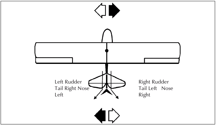
Fig. 17 Effect of Rudder.
- Flaps: Flaps are another aerodynamic control surface found on an increasing number of microlights. Flaps work in the same way as ailerons and vary the wing camber, they provide a decrease in landing speed when deployed whilst retaining maximum speed when up. The flaps on each wing are connected so that they can be raised and lowered together (as opposed to ailerons where one goes up while the other goes down). By increasing the effective lift, flaps reduce the stalling speed and enable the microlight to fly at lower airspeeds. Also, by increasing drag flaps enable the aircraft to glide at a steeper angle with no increase in forward speed. See Fig. 18. Microlights utilise flaps either inboard of the ailerons or in combination with the ailerons called Flaperons. Flap use sometimes causes a pitching moment by shifting the wing's centre of pressure. Flaps are normally partially down to shorten the TakeOff roll, and fully down to shorten the approach and landing. There is a maximum speed limit for flap lowering to avoid overstressing the mechanism, refer to your aircraft's handling notes for optimum settings and ecommended speeds.
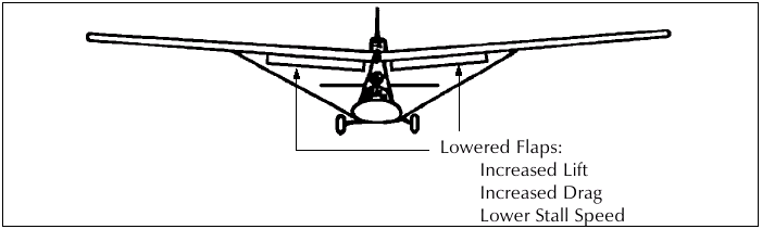
Fig. 18 Effect of Flaps.
- Trim devices: Some microlights have the means to reduce the manual loads in the controls in some modes of flight. For example, an elevator trim can be used to ease the backpressure required to maintain a climb, or could be altered to provide handsoff level flight. On some aircraft this may be achieved by physically moving the entire control surface to get the desired effect. Sometimes a spring tension is applied to the surface or control linkages/cables. Another is the trim tab which is a small moveable surface attached to the control surface. Moving this tab surface alters the lift characteristics of the control surface it is on, thus changing the stick loads felt by the pilot. Trim is used each time the aircraft attitude is changed, to provide hands-off flight in each new attitude.
- Throttle: The throttle controls power output from the engine. Full power is required for take-off and maximum climb, reduced power for cruise, and considerably less for descent.
The throttle controls rate of climb and descent.
Further Effects of controls
In addition to the primary effects of controls already mentioned, each control application will produce a secondary effect which must be considered.
- Aileron: Use of ailerons will produce yaw. This is due to the uneven drag of the up and down ailerons and is called adverse yaw or aileron drag.
- Elevators: Use of the elevators alters the angle of attack of the wing, and this effects the speed of the microlight.
- Rudder: Use of the rudder produces yaw. This yaw increases the speed of the wing opposite the direction of the yaw which produces greater lift on that wing thus inducing roll in the same direction as the yaw.
- Throttle: Increased power normally causes a "pitch up" moment with yaw, while decreased power causes a "pitch down" moment with yaw. The greater the power variation, the greater the effect. Increased throttle also produces torque which maust be balanced by rudder. The pitch response to throtle is also dependent on the thrust line- in a microlight with a high thrust line, applying full power may cause a noticeable pitch down response.
Effect of Airspeed:
- High airspeed all controls firm and more effective.
- Low airspeed all controls sloppy and les effective
.
Effect of propellor slipstream:
- High power rudder and elevator firm and more effective.
- Low power rudder and elevator sloppy and less effective.
Ailerons are outside of the propellor slipstream and give a good indication of airspeed.
STRAIGHT AND LEVEL FLIGHT
We have already seen that in straight and level flight, the four forces acting on the microlight are balanced with their opposite, (assuming a constant airspeed). Level flight is possible at any speed above the stall speed, right up to the maximum attainable in level flight. Let us look at a microlight in level flight at full power. The four forces are balanced, with thrust equalling drag, and lift equalling weight. If we were to reduce power to, say 75%, what happens? As the thrust is reduced, drag slows the aircraft down until thrust equals drag again.
If we had kept the angle of attack the same, the aircraft would now begin to descend because at the same angle of attack the lower speed will produce less lift. So, in order to maintain level flight at this lower speed, we have to increase the angle of attack to produce the lift needed.
This process continues as we slow down further. The slower the airspeed, the greater the angle of attack needed to produce the lift needed for level flight. However by increasing the angle of attack remember we are also increasing the drag created by the wing. Excessively high angles of attack with low airspeed can result in a stall and spin.
We can counter this by applying more power, but if the aircraft is in slow flight with a nose high attitude then there comes a point where there will be insufficient extra power available. This situation is called "flying on the backside of the power curve" or "Deadmans Curve!" and occurs when the power available is insufficient to overcome the drag when flying at a high angle of attack.
The situation is most likely to develop if the pilot throttles back while climbing and then at a slower airspeed, and in a nose high attitude, opens the throttle again and the aircraft does not respond as expected. The recovery is simply to lower the nose allowing the airspeed to return to a higher figure. The danger of the above situation is much greater if near the ground as there may be insufficient height for recovery. Recovery will mean a loss of height.
A similar situation could develop if the pilot attempts to initiate a climb immediately after take-off and before the aircraft has accelerated to an airspeed that will allow it to climb safely. The recovery is to lower the nose, reducing the angle of attack, and waiting for the airspeed to return to a higher figure.
The purpose of this section is to point out that a high power setting does not necessarily mean flight at high speed. It is the elevators and thus angle of attack which is primarily responsible for speed control. Remember, flight is possible at low speed and high angle of attack, high speed and low angle of attack, and an infinite number of combinations of angle of attack to obtain the same value of lift.
CLIMBING
We have already seen that a climb will result if lift exceeds weight. As long as there is more thrust available than that required for level flight, then the microlight can be made to climb. The more excess thrust available the greater the rate of climb possible. When we raise the nose increasing the angle of attack to produce the extra lift to initiate the climb, we know of course that the airspeed will drop and then reduce lift as we do so. For this reason, the extra power needed to sustain the climb should be applied just before raising the nose. See Figure 19. When returning to level flight from a climb it is necessary to lower the nose and build up airspeed before reducing power. See Figure 20.
When making changes in altitude or reestablishing level flight from a climb, use the following:
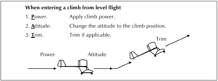
Fig. 19
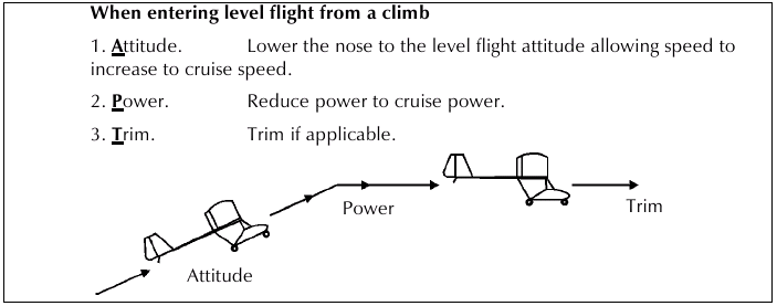
Fig. 20
- Best Rate of Climb (altitude gained in a given time)
At climb power, every aircraft has a climb airspeed which will give an optimum rate of climb. This airspeed corresponds to an angle of attack which provides the most lift for the least drag (best L/D). In this configuration the aircraft will climb the highest in the least time. If a rapid climb is desired, to climb at above the optimum speed will reduce the rate of climb, since there is thrust being wasted on airspeed rather than lift production. Likewise, attempting to climb at below the optimum speed will reduce the rate of climb as the extra drag of the higher angle of attack requires more thrust (which is not available) to counter it. See Figure 21. This airspeed is normally also the best glide airspeed.
- Best Angle of Climb (altitude gained in a given distance)
The best (steepest) angle of climb will be achieved with climb power at an airspeed a little less than that for the best rate of climb. This airspeed corresponds to an angle of attack which produces the most lift but higher drag. Here again, maintaining the right airspeed is important if the best angle of climb is desired. This airspeed is normally also the minimum sink rate airspeed.
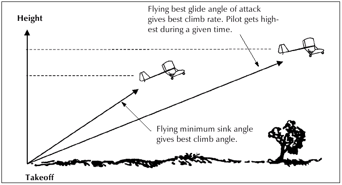
Fig. 21 Best angle of climb versus best rate of climb.
- Factors Affecting Climb Performance
An increase in weight will reduce rate and angle of climb. Rate and angle of climb will reduce with increasing altitude as engine, propeller and airfoil performance suffers from reduced air density. Climb performance will be reduced in warm and humid air.
The use of flaps can allow for an increase in the angle of climb and a reduction in the climb airspeed.
Best angle of climb would only be used after takeoff from a short field where obstacle clearance is important and once clear, best rate of climb airspeed would be resumed.
Check your owner's manual for any best climb speed given. The usefulness of such information is dependent on the accuracy of your air speed indicator as a few knots variation either way could greatly detract from the desired performance. Care should be taken in some aircraft to avoid overheating the engine in a climb. If necessary, level off occasionally or increase airspeed to aid cooling.
It must be stressed that the correct airspeeds be maintained in order to climb efficiently. Holding the nose as high as possible with full power does not mean the microlight is climbing well ! Indeed it may be descending! Maintain a healthy margin above the stall speed during the initial climb, until well clear of the ground.
DESCENDING
A microlight will descend from level flight any time there is insufficient thrust to maintain level flight and/or the weight of the aircraft is more than the lift being produced.
From level flight we can descend either by lowering the nose, reducing power, or both. It can be seen that descent is possible at any power setting and this is because gravity is the force naturally trying to make the aircraft descend at all times.
From level flight at cruise speed, for example, if we lower the nose the angle of attack is reduced and the reduced lift initiates the descent. If we have not reduced the power, the speed will increase considerably as we now have both thrust and gravity assisting us in our downward path.
When the forces of thrust and gravity equalise with the drag of our new speed, the rate of descent will stabilise.
Descents are usually made with reduced power because in this way there is less increase in speed. During a descent with power on, the aircraft may reach its maximum permissible speed fairly easily and at a shallower angle than with power off. When entering a descent from level flight, first reduce power, maintain height until airspeed reaches descent speed, then lower the nose for the descent and trim ( if applicable). Periodical y warm the engine during long descents at low power to avoid overcooling and/or spark plug fouling.
The use of flaps can allow for an increase in the angle of descent and a reduction in the approach airspeed.
When making changes in altitude or reestablishing level flight from a descent, use the proceduers shown in Figues 22 and 23.
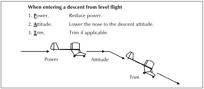
Fig. 22
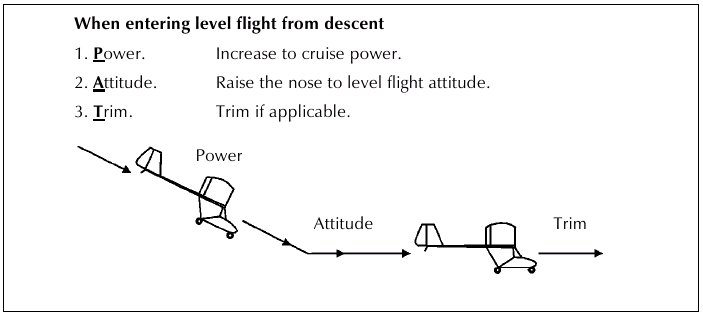
Fig. 23
GLIDING (Figure 24)
If we look at our four forces of flight we see that with the power off, gravity takes over the job of thrust in providing our forward momentum and the flight path is downward.
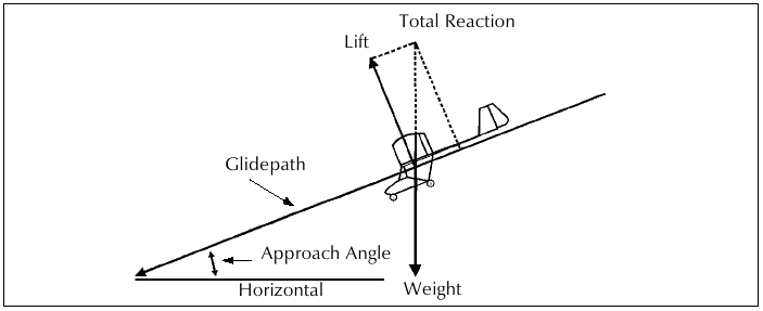
Fig. 24
The pilot still has complete control with the exception of being able to climb or maintain height.
At a given airspeed, the most lift for the least drag will be produced by the wing and at this speed the microlight wil glide the greatest forward distance for the least height lost (best L/D speed).
At another slightly slower speed, more lift will be produced, but at the cost of more drag, resulting in the least rate of descent possible with power off. This speed gives the best duration in the air but NOT distance. See Figure 25.
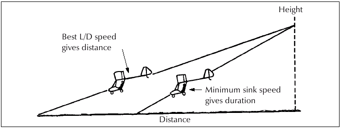
Fig. 25
The correct use of flaps will reduce the best L/D speed and sink rate.
Consult your owner's manual for the best L/D and best sink rate speeds.
Care must be taken to maintain sufficient airspeed in the glide, especially near the ground as stall recovery without power requires considerably more altitude.
TURNING
Two fundamental laws of mechanics must be borne in mind when considering medium turns.
Firstly, a microlight will continue in a straight line at a constant velocity unless acted upon by an external force.
Secondly, the acceleration applied by an external force is inversely proportional to the mass. In other words, the heavier the microlight the larger the force required to change direction and the more resistance to that change in direction (i.e. inertia).
At this point it is appropriate to mention that a pilot must not enter a turn unless a proper lookout has been done.
"Proper lookout means that the pilot has checked to the right, centre, left, above and below, before changing direction or altitude."
When flying a high wing microlight, it makes good sense to "clear the turn" first. This is simply done by first momentarily raising the wing on the inside of the intended turn and checking for traffic in that direction. If it's clear, proceed with the turn. Low wing microlights don't need to "clear the turn", since the inside wing clears the view as it drops, but you must always check before initiating the turn.
A turn is produced by lift pulling the microlight from its straight course while overcoming gravity.
Thus, if altitude is to be maintained in a turn the wings must produce lift equal to the weight of the microlight plus the centrifugal force caused by the turn. See Figure 26.
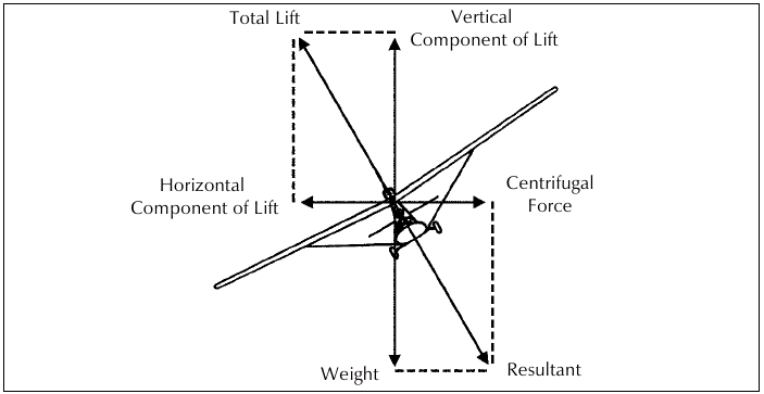
Fig. 26
The increase in lift is normally obtained by increasing the angle of attack, the airspeed or the power (or all three). So it is inclining the lift that produces the turn. If a turn is made during a climb, the rate of climb will decrease as some of the available lift is being used to effect the turn, rather than help the climb. Therefore, whilst climbing, only shallow angles of bank should be used so that a positive rate of climb can be sustained.
To initiate a medium turn from level flight the aircraft must be rolled in the desired direction with the ailerons. It is here that adverse yaw may appear.
Adverse or Aileron Yaw as it is often called, is a yaw produced by the ailerons. Remember in the effect of controls section, it was stated that the down going aileron increases the curvature (camber) and thus the lift. Unfortunately, a further effect of this is increased drag. Therefore, the wing with the lowered aileron (which produces more drag than the raised one), causes a yaw to that side, which is the opposite side to the direction of the desired turn.
For this reason, it is important to prevent this yaw and maintain balance with the rudder in the direction of the turn (with reference to the slip indicator, or yaw string), i.e. no slipping or skidding. See Fig. 27.
So, here we are with the microlight rolled to about 30° angle of bank and the slip indicator indicating balanced flight. As we rolled, the nose wil have wanted to drop a little and this is prevented with aft stick which increased the lift (angle of attack). Now the microlight will be turning.
- The speed is controlled with the elevator
- The angle of bank with the ailerons
- The balance with the rudder
- The rate of climb or descent is controlled with throttle.
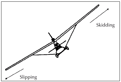
Fig. 27
To stop the turn, roll the aircraft level with the ailerons while maintaining balance with the rudder and keeping the nose from rising or falling with the elevator. In the turn the outside wing travels through the air faster than the inside wing so it will develop more lift and tend to roll the microlight into the turn even more. This has to be countered with opposite aileron once in the turn.
LOAD FACTOR
- Effect of Turn on Load Factor
Since a turn is produced by inclined lift pulling the microlight from its straight course while overcoming gravity, if altitude is to be maintained the wings must produce lift equal to the weight of the microlight plus the centrifugal force caused by the turn.
As the bank gets steeper the centrifugal force builds up. Therefore, any time the microlight flies in a curved path at a constant altitude, the load supported by the wings is greater than the weight of the microlight, thus the load factor increases. See Fig. 28.
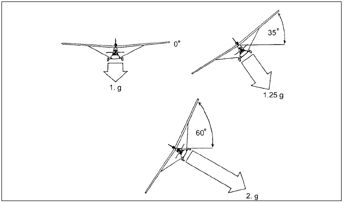
Fig. 28
- Effect of Load Factor on Stall Speed
With an increase in load factor there is an increase in stall speed. The load factor increases when a microlight follows a curved flight path (turns), pullouts from dives, or sudden application of backpressure on the control stick. Consequently, the stalling speed also increases in these same manoeuvres.
- Effect of Turbulence on Load Factor
Severe vertical gusts impose loads on the wings which can be excessive. These gusts cause a sudden change in angle of attack, resulting in large wing loads which are resisted by the microlights inertia.
When encountering strong turbulence, reduce airspeed. This enables the airframe to withstand the forces more easily.
Assuming a constant airspeed, the load factors at various angles of bank will be:
| Angle of Bank | Load Factor |
|---|---|
| 0 | 1g |
| 35 | 1.25g |
| 50 | 1.5g |
| 60 | 2g |
| 75 | 4g |
| 83 | 9g |
The increase in load factor causes an increase in stalling speed:
| Angle of Bank | Stalling Speed Increases by |
|---|---|
| 60 | 40% |
| 75 | 100% |
| 83 | 200% |
As the loading is increased, the stalling speed increases and the microlight becomes less manoeuvrable. The pilot wil feel the force pushing him/her down into the seat.
At high loadings, the pilot's vision may be impaired and at about 5g or 6g the pilot may "black out".
During recovery from steep dives, al ow for the extra height loss due to inertia and also the higher stal ing speed.
STEEP TURNS
The principles of flight relating to steep turns are the same as those for medium turns. With a steeper angle of bank, the rate of turn is greater. With medium turns it was mentioned that extra lift had to be produced to maintain height and it is the same for steep turns, although considerably more lift is needed. To achieve this, as the bank is applied, the power is increased to help counter the increased drag of the high angle of attack. Altitude can be easily gained or lost, and should be controlled with the aileron by varying the angle of bank.
Available power is usually the limiting factor in steep turns and few microlights can sustain angles of bank greater than 50 60 degrees without losing height.
Just as in any other turn, airspeed is still controlled with the elevator, angle of bank with the ailerons and balance with the rudder.
The increased lift required during turns increases the load factor and, as previously discussed, this increases the stall speed:
| Angle of Bank | Loading | Increase in Stall Speed |
|---|---|---|
| 30 | 1.16 times | 10% |
| 60 | 2 times | 40% |
| 75 | 4 times | 100% |
The increase in loading stresses the microlight airframe and there is a design limit each type can safely handle. Find out the extent of your aircraft's ability to withstand this g loading from the owner's manual.
The pilot, of course, is also subjected to this loading in turns and it is felt as a pressure pushing one into the seat. The amount of this g force the body can handle varies from person to person, but most people feel decidedly uncomfortable at 3g.
It should be pointed out that for brief periods one can cope with quite high loadings on the body and it is extremely difficult to judge this accurately. Therefore, a careless pilot could easily overstress his microlight momentarily with improper use of the controls, and not realise it.
The increase in stall speed dictates a higher entry airspeed into the steep turn. Failure to maintain sufficient airspeed in the turn could result in a stall. To stall in a steep turn invariably results in a rapid change in direction and loss of height (and may possibly develop into a spin).
More height may be needed to recover from such a stall and steep turns mustbe avoided near the ground, particulalry the turn onto final approach.
To summarise, an increase in rate of turn requires:
- Before entering any turn LOOKOUT !!!
- Increased angle of bank.
- Increased angle of attack.
- Increased power.
which results in:
- Increased wing loading.
- Increased stall speed.
- Decrease in air speed (due to extra drag of high angle of attack).
- Effect of speed on Load Factor
The degree of excess load the microlight is exposed to depends on how fast it is flying.
At slow airspeed, the available lifting force of the wing is only a little greater than what is needed to support the weight of the microlight. As a result, the load factor cannot become excessive, even if the controls are moved abruptly.
At high airspeed, the lifting force of the wing is so high that a sudden gust or sharp movement of the controls could increase the load factor beyond safe limits.
"At high airspeed avoid rough air and abrupt, coarse control movements."
SPIRAL DIVE
As mentioned in the section on turning, the nose must be raised to provide the extra lift needed to maintain level flight in the turn. However, if the correct nose attitude is not held, and the nose is allowed to drop, the microlight will begin to descend (and rate of turn will be less).
A descending turn like this can develop into a spiral dive.
There is nothing wrong with a spiral dive as long as the airspeed is kept within limits, the loading is not excessive and the correct method is used to recover from it.
Unfortunately, the spiral dive can be a problem for new pilots as they make turns. If they allow the nose to drop too much in the turn, there comes a point where trying to raise the nose with elevator merely tightens the descending turn. This is not a big problem at shallow angles of bank, but if ever in a descending turn, the development of a spiral dive is possible.
Symptoms of a Spiral Dive
- Nose below the horizon.
- Airspeed increasing.
- Moderate to steep angle of bank and turning.
Confirmation that you are in a spiral dive will occur if you try to raise the nose to recover from the dive. There will be a tightening of the turn and increased G loading felt without any recovery from the dive. Your instructor will demonstrate this condition and the correct recovery which is:
"Roll the wings level with the ailerons, reduce power, and ease out of the dive."
By rolling level first, the turn is eliminated leaving the microlight in a dive, which is recovered by raising the nose (being careful not to do so too abruptly, thus overstressing the airframe). Pitching up too quickly can also cause a high speed or 'shock' stall.
STALLING
We have already seen that by forcing the angle of attack of the wing too high the smooth airflow over the top surface of the wing is destroyed and lift is lost. In this condition the wing is said to have stalled.
Symptoms of the Stall
- Low airspeed (generally, unless the angle of attack is forced too high at a high airspeed).
- High angle of attack (note this is wing angle of attack and not the machines attitude).
- Sluggish controls.
- Buffeting caused by turbulence over the wing and the tail surfaces.
- Nose and sometimes wingdrop. (Some microlights have an indistinctive and mushy stall without appreciable nose or wing drop.)
Typical stall from Level Flight
With the increase of angle of attack, the airspeed will reduce, providing the first clue to the pilot through both the airspeed indicator and the sound and feel of the airstream diminishing.
As the airspeed reduces further the controls become sluggish. Normal movements of the controls provide only poor response. Depending on the aircraft, it may feel nose heavy, requiring effort to hold the nose up.
With the angle of attack getting very near to stalling point, the smooth airflow over the top of the wing may begin to break up from the trailing edge, causing a turbulent flow over the tail surfaces which may be felt as buffeting in the airframe and controls. On some aircraft it is possible to see the wingcovering wrinkle as the flow becomes turbulent . The microlight is now very near the full stall and any further increase in angle of attack will stall the wing. The instantly this occurs, the controls will seem to have little or no effect, as airspeed is very low. The nose will want to drop and a wing may drop also. See Fig. 29.
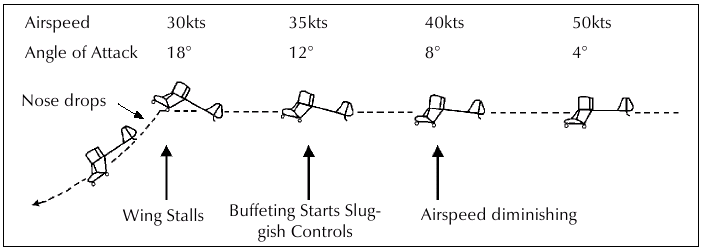
Fig. 29 The Wing Drop
At the point of stall , if one wing produces more lift than the other, one wing may drop. The nose will yaw towards the lower wing and the nose will drop sharply as the angle of bank increases.
The angle of attack on the upper wing is less than that of the lower wing and this may actually unstall the upper wing. The upper wing is moving faster at a lower angle of attack, the lower wing is moving slower at a higher angle of attack, and this begins a brisk rotation, called autorotation. From this point some microlights may enter a spin, continue autorotation or enter a spiral dive.
Recovery from the Stall
Al that is required to unstall the wing is to reduce the angle of attack to restore smooth airflow over the wing.
To minimise the height loss of the stall recovery, power should be used to assist. Control will be regained faster with less loss of height. The slipstream over the wing (with tractor mounted engines) may smooth the airflow and help reduce the relative angle of the airflow.
Therefore, recovery is a matter of lowering the nose then applying sufficient power to regain flying speed and control, and recovering from the ensuing dive. Rudder must be used to keep the aircraft straight. If a wing drops at the point of stall, the ailerons must NOT be used to raise the lowered wing as the downward positioned aileron further increases the angle of attack of that part of the wing, resulting in further loss of lift which can result in greater roll and subsequent autorotation . The correct recovery for a wing drop stall is to prevent further yaw with the rudder, then lower the nose and apply full power. As control is regained, level the wing and recover from the dive.
SPINNING
From a stalled condition, some microlights may be capable of entering a spin which is a stalled autorotation. The spin may develop from a stall where there is Associated Yaw. See Figs. 30 & 31. In most microlights, a spin is a fairly unlikely event, usually requiring gross mishandling of te controls. During the spin, the microlight is in a fairly steep nose down attitude, autorotation continue and the airspeed is low, and the aircraft is pitching, rolloing and yawing all at the same time.
The dangers connected with spins are:
- Considerable height is needed for recovery.
- Not all microlights are designed for spinning, therefore, check the manufacturer's literature for spin details, including any recommended recovery technique.
- Pilots who have not received comprehensive spin training may instinctively hamper or prevent recovery by incorrect recovery technique.
While the spin is not the most pleasant manoeuvre for some, pilots should be encouraged to get spin training in an aircraft cleared for spinning.
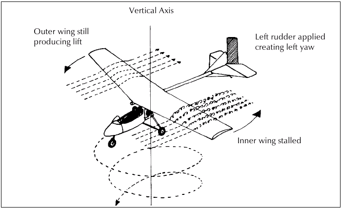
Fig. 30 Spin entry
Attach:tmfig031.png Fig. 31 The sequence of a spin. The microlight is stalled and rotating around a small radius from the vertical.
Since yaw is the cause of a spin, opposite yaw will stop the spin.
Recovery:
- Ensure throttle closed.
- Centralise ailerons.
- Apply full opposite rudder.
- Ease the stick forward.
- When spinning stops, centralise the rudder.
- Level the wings and ease out of the dive.
- Reapply power as the nose approaches the climb altitude.
Note: With a forward centre of gravity, the spin wil be steeper and less stable, with easier recovery. With an aft centre of gravity, the spin will be flatter and more stable, with a slower (or even impossible) recovery. Never attempt to spin any aircraft not cleared to do so by the manufacturer, or without proper spin training.
Don't be a test pilot!!!
Factors Affecting the Stall
- Weight: Increased weight(such as passenger and baggage) requires more speed to produce the greater lift needed at all angles of attack. The stalling speed will be higher.
- Power: At high angles of attack, the angle of the thrust line may contribute to the lift. Tractor mounted engines with the slipstream over the wings may help prevent the airflow breaking up and provide more lift.
- Flaps: With use of flap, more lift is produced at a lower airspeed, thus reducing the stall speed.
- g Loading: The stalling speed will increase with loading such as in a turn or during sudden pitching up in a dive recovery.
We have looked at the stall from level flying but, in fact, a stall is possible in any attitude of flight relative to the horizon. No matter where the nose is pointing the aircraft will stall if the wings are presented at too great an angle to the relative airflow.
Furhter reading: Kermode is recognised as the guru of Principles of Flight.