
FLYING IN WIND
Wind is simply a mass of air moving over the earth's surface. An airborne microlight is flying in that moving mass of air. The wind has no effect on the microlight itself (turbulence excepted see turbulence section) but does have an effect on its path over the ground and its speed relative to the ground (ground speed).
It is vital to understand the difference between airspeed and groundspeed.
- Airspeed is the speed of the microlight through the air.
- Groundspeed is the speed of the microlight over the ground.
The two are completely separate and different values!
Airspeed is an important factor in controlling the microlight in the air and groundspeed is only a measure of progress over the ground, having no relevance to the flying characteristics of the microlight whatsoever.
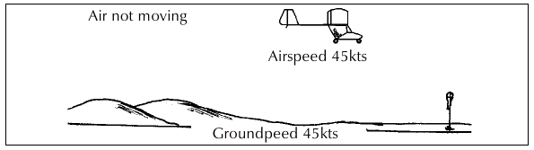
Fig. 59
Effect of a direct headwind
Flying into a direct headwind reduces the groundspeed by a factor equal to the wind speed.
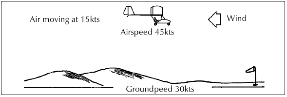
Fig. 60 The reduced groundspeed means more flight time needed to reach a destination (i.e. more fuel required) and there wil be an illusion of slow airspeed.
Effect of a direct tailwind
A direct tailwind increases the groundspeed by a factor equal to the wind speed.
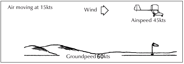
Fig. 61
The increased groundspeed gives a faster time to reach a destination and gives an illusion of faster airspeed. This illusion of extra airspeed will be more pronounced when near the ground and can be dangerous if the pilot slows down to what his normal speed "looks like" in nil wind, thus possibly resulting in a stall. During a crosscountry, every pilot loves a tailwind.
CROSS WIND
A wind blowing across the desired flight path (crosswind) will carry the microlight off the desired path in the direction the wind is blowing.
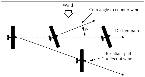
Fig. 62
To counter the effect of a crosswind a balanced turn should be made into wind until the effect of the crosswind is halted and the track made good is along the intended flight path. This is called crabbing. See Fig. 62.
Initially it may seem strange to have the nose pointed away from your destination, but correcting for drift in this way ensures the quickest time between points.
Of course, there are variations of headwind, tailwind, and crosswind components.
Effect of Wind on Climb
Firstly it must be stated that wind from any direction will not have any effect on rate of climb. However, wind will effect the angle of climb.
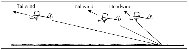
Fig. 63 Effect of wind on climb angle.
Climbing with a tailwind means the groundspeed is increased while the rate of climb remains the same as normal. This translates to a flatter climb angle relative to the ground.
A pilot climbing with a tailwind has to remember there is going to be an illusion of speed and the aircraft may feel as though it is not climbing properly. Therefore the pilot must be sure to maintain normal climb airspeed, and beware that the flatter climb angle could affect obstacle clearance. Rate of climb is unaffected.
Climbing with a headwind means the groundspeed is reduced while the rate of climb remains the same as normal. This translates to a steeper climb angle relative to the ground. Rate of climb is unaffected.
Effect of Wind on Descending
The same principles apply to a descending microlight. Angle of descent relative to the ground will change, while rate of descent will not.
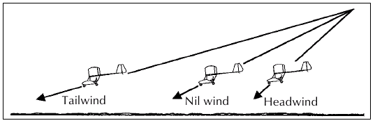
Fig. 64 Effect of wind on descent and glide angle.
Effect of Wind on Gliding
The same principles apply to a gliding microlight. The important thing to remember is that a headwind will greatly reduce the distance a microlight is capable of gliding, while a tailwind will extend the glide distance. These are vital considerations during a forced landing.
Effect of Wind on Turning
If you were to observe from the ground, a microlight with a smoke generator making a 360° turn of constant angle of bank and rate of turn, the smoke would describe a perfect circle even if there was a ten knot wind blowing. However, the microlight's ground track would look very different!
During the turn in the wind, the microlights ground track was affected by the wind. Let's use an example of a microlight flying with a direct crosswind from the path over the ground. If the pilot commences a constant rate turn to the left, the microlight will be helped along its groundpath to the left by the wind from the right.
Visually, it will seem that the microlight is accelerating rapidly and turning too fast for the angle of bank (slipping). The pilot may even feel that the aircraft is losing height.
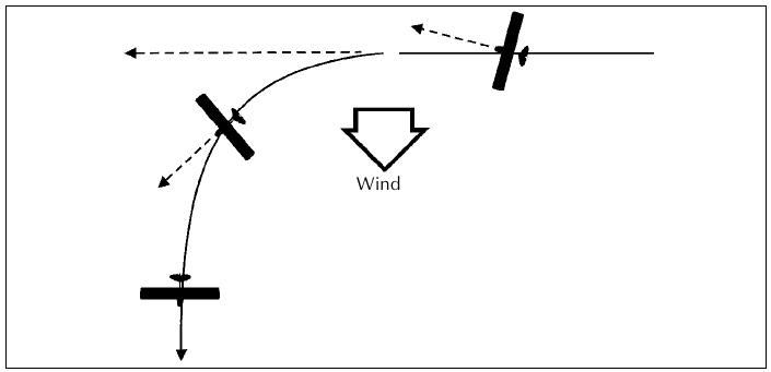
Fig. 65
Now the microlight is in the downwind portion of the turn and it seems to be going very fast because the ground is flowing by quickly. As the turn continues it will appear as though the aircraft is sliding out of the turn and that it is not turning very wel . The pilot may tend to steepen the bank.
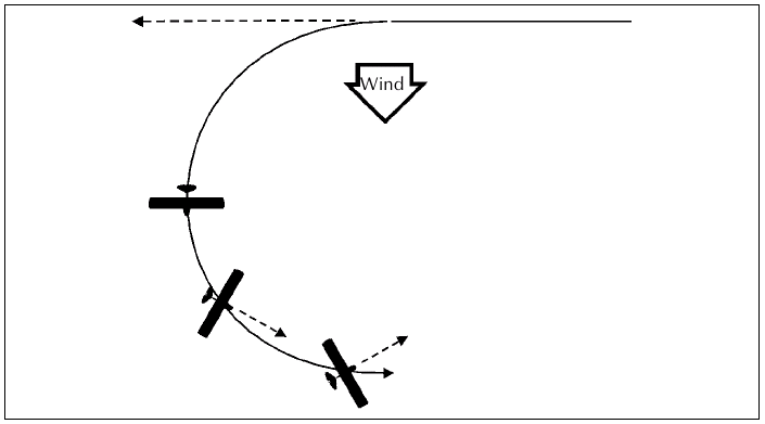
Fig. 66
The microlight is now in the crosswind position again and it will seem to be flying sideways (skidding). As the turn continues into the upwind position it will appear to be slowing as the groundspeed reduces.
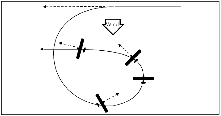
Fig. 67 The turn is completed with another apparent slip to the left as it resumes its crosswind course.
We can now see that reference to the ground gives a false impression of what the aircraft is experiencing while making turns in the wind. It is vital to fly balanced, correctly banked turns at the proper airspeed, disregarding any illusions gained from looking too closely at the ground.
An aircraft is flown in relation to the air it is flying in, and not by reference to the ground.
However, there are times when we wish to fly a course in relation to the ground and it is here that we use our knowledge of how the wind affects our groundspeed and ground track, to adjust our path through the air to achieve the desired result.
The constant radius turn is an example. This is a turn where the desired result is a turn around a point on the ground which gives a ground track of constant radius around that point. See Fig. 68.
In still air this is relatively easy as a constant rate turn will give the constant radius ground track around the point. If there is a wind blowing however, the turn will have to be modified, to compensate for the effect of the wind.
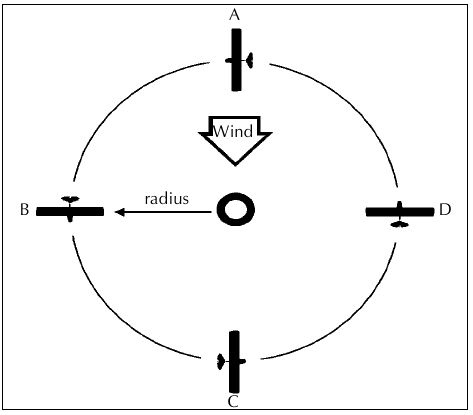
Fig. 68 Constant radius turn.
In our figure the turn is commenced at point A being careful not to use too much bank as the wind aids our path to point B. At point B the angle of bank will have to be increased until at point C the bank is at its steepest and starts to reduce again approaching point D and to point A again.
Remember:
- maintain correct airspeed and balance at all times.
- don't be fooled by illusions caused by groundspeed or ground track.
- use your knowledge of the effects of wind to your advantage.
- the closer one is to the ground, the more dramatic the effects of wind appear.
TURBULENCE
If the atmosphere in which we flew were always still, no pilot would have his microlight bounced around the sky. As it happens, our sky is almost always in motion. Some of this motion is smooth and some is quite abrupt or violent.
There are two types of turbulence Mechanical and Thermal (or convection).
Mechanical Turbulence
If you have ever watched the water in a shallow stream, swirl and bubble over rocks submerged or partly submerged in it, then you have seen a close approximation of the action of air flowing over similar objects on the earth's surface.
Unfortunately we cannot see the air, but we can make a fairly accurate guess of the degree and type of turbulence to be expected for a given situation. As the microlight flies into disturbed air, its flight path is affected accordingly.
Whenever possible, try to observe the effects of mechanical turbulence by watching smoke or the movement of thistle "fairy" seeds as the breeze passes over the landscape. Even in light winds you will be surprised at what movements in the air these indicators show.
In an open paddock with some obstacles in it (barn or row of trees etc) one can stand in the lee and feel the turbulent flow, or wind shadow.
An awareness of mechanical turbulence is important, especially as many microlight operations involve airstrips closely surrounded by turbulence producing objects and terrain, as opposed to the wide open space of big airports.
Let's look at some typical examples of mechanical turbulence.
Remember, any time the air is made to flow over or around an object, the airflow will be affected. Where the airflow is required to change direction abruptly, the flow will break up and become turbulent.
The extent and severity of the lift and sink in mechanical turbulence, increases sharply with increasing wind strength.
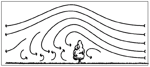
Fig. 69 Wind flow over a row of close thickly leafed trees.
Wind flowing over these trees (Fig. 69) will be forced to go over the top as not much air will be able to flow easily through. This will cause an abrupt change as the air rises over the row, and then behind will be an area of turbulent air as the flow breaks up. As a general rule allow at least 6 or 7 times the height of the trees downwind to be free of the turbulence in moderate winds.
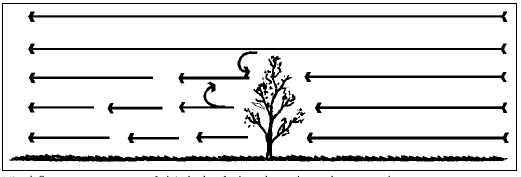
Fig. 70 Wind flow over a row of thinly leafed or less densely spaced trees.
If the trees are spaced apart or thinly leafed, then the turbulence may be reduced as a significant flow of air will be able to pass through the trees.
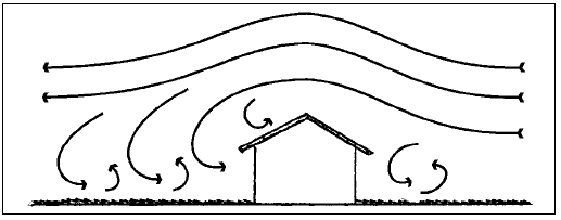
Fig. 71 Wind flow over building. This is much the same as over trees.
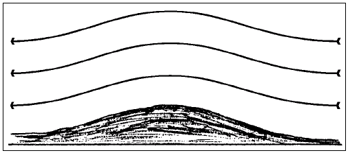
Fig. 72 Wind flow over terrain. Wind flow over smooth gentle hills may produce little or no turbulence, only lift upwind and sink down wind.
Effect of Wind Speed on Extent of Turbulence
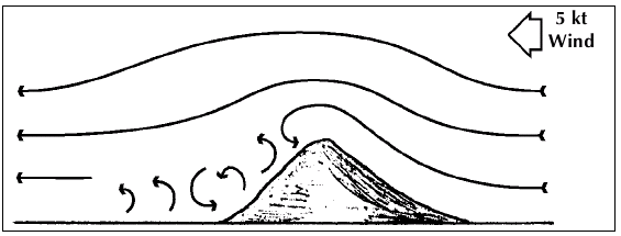
Fig. 73 Effect of 5 kt Wind.
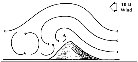
Fig. 74 Effect of 10 kt Wind.
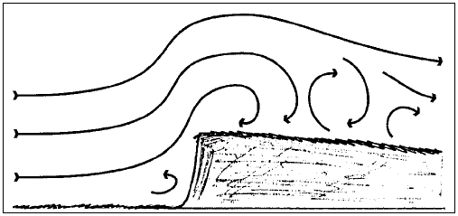
Fig. 75 At the base of a cliff there may be a turbulent area and almost certainly behind the lip of the cliff it will be very dangerous.
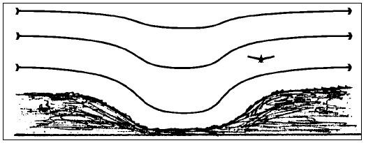
Fig. 76 When flying along a valley with the wind blowing across it, stay on the downwind side where the air will be smoother and rising.
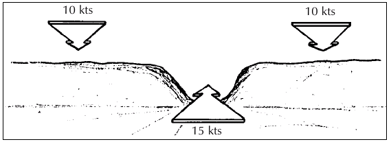
Fig. 77 Wind speed increases when flowing through gaps in ranges.
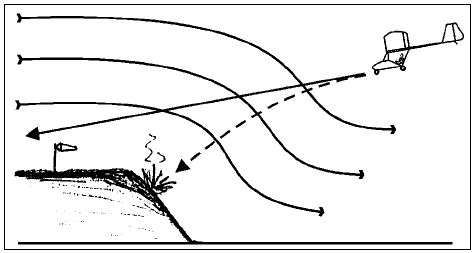
Fig. 78 With a drop of the landing end of a runway, there is likely to be sink which will af ect the glidepath.
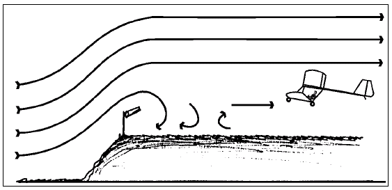
Fig. 79 Likewise, with a drop off the takeoff end of the runway there will be sudden lift and even turbulence back from the edge.
Flying into Lift and Sink
Flying into lift (rising air) momentarily increases the angle of attack of the wing as the relative airflow is changed. This will cause a drop in airspeed due to the increased drag of the higher angle of attack. If the lift is sufficient the microlight will rise.
Flying into sink (descending air) momentarily reduces the angle of attack of the wing as the relative flow is changed. This will cause an increase in airspeed due to the less drag of the smaller angle of attack. The microlight may descend.
When encountering lift or sink and the airspeed is altered, the microlight will try to return to its previously trimmed value.
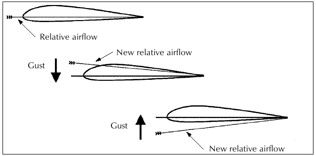
Fig. 80 These vertical gusts causing rapid changes in angle of attack, impose stress on the microlight airframe. The load factor alters.
Wind Shear/Gradient
Due to the friction the air experiences flowing over the surface of the earth, the wind speed near the ground is usually less than that at altitude. These effects are usually (but not always) small when the winds are light, but become greater when the winds are strong. Added to this is the effect of mechanical down draughts. Down draughts can cause a sudden decrease in the microlights rate of climb immediately after takeoff, or a sudden increase in the rate of the descent during the approach to landing.
The possibility of meeting such conditions creates a need for all pilots to be aware of the hazards associated with these variations in wind velocity during the takeoff and landing stages in particular.
Any variation of airflow velocity, whether it be horizontal or vertical, produces a shearing action between layers of air, hence the term "wind shear". The effects of wind gusts and associated turbulence can be appreciated fairly easily, but changes in the horizontal wind speed and/or direction will require more explanation. Lift is the force which overcomes weight and an aircraft obtains this lift from the angle of attack at which the wings are presented to the airflow and the speed at which it is flown. The higher the airspeed, the greater is the lift. Therefore, any sudden change in the wind speed or its direction relative to the aircraft will affect the lift being produced.
A microlight descending through layers of air where the wind speed is decreasing rapidly, will be penetrating a region of wind shear/gradient, the effect of which will temporarily lower the airspeed. Less lift will be produced and the microlight will descend more quickly.
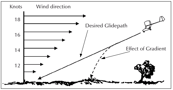
Fig. 81
When the gradient is gentle the pilot will have no trouble in lowering the nose of the microlight to regain its original airspeed, but if the wind gradient is rapid and pronounced he will need to act very quickly to readjust the microlights' airspeed, and also increase engine power to help arrest the descent.
Sometimes the effects of mechanical turbulence, thunderstorm activity, or an inversion, can create the effect shown in the illustration below.
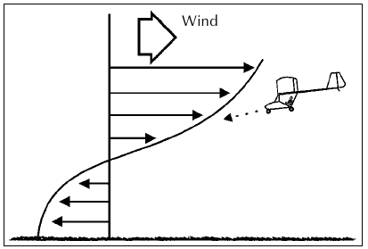
Fig. 82 In this case the wind direction has become temporarily reversed near the ground requiring very quick reactions from the pilot during the takeof or landing phase.
Wind shear is a particularly common occurrence during thunderstorm activity, and can be met on any side of such an area. The wind shift line (or gust front) can precede a storm by 15-20 miles, consequently, when thunderstorms are within this distance wind shear hazards must be anticipated at any time.
A further note in relation to wind shear is that it is not necessarily associated with strong winds.
For example, when a temperature inversion exists, a common situation is for very light or zero wind to be present at the surface although winds just above the inversion layer may be moderate to strong.
Thermal or Convection Turbulence
This is caused by the heating of the earth's surface which in turn heats the air in contact with it, and causes convection currents which over land reach their maximum intensity about midafternoon. If the rising air is moist, convection cloud will form cumulus (Cu), strato cumulus (Sc), or possibly in very unstable conditions, cumulonimbus (Cb).
On days when these clouds are present expect to encounter both lift and sink associated with the convection process. In general, this lift and sink is fairly mild and the lift can even be used by a skilled pilot to enhance climb performance or even to sustain lift. However, when such thermal activity is vigorous the conditions can become very violent. The lift associated with the abovementioned clouds can be stronger than the microlight's ability to descend through it.
Thus, there can be a very real danger of being "sucked into" cloud, (discussed in meteorology) so as a general rule keep well clear of fastgrowing towering cumulus type clouds.
With the exception of thunderstorms or line squalls, the effects of turbulence are usually greatest near the surface or just below large cumulus clouds. These regions can normally be avoided during enroute flight. However, the altitude band in which microlights operate is somewhat restricted, and additional care will be needed when mountains or high hills have to be traversed.
In these regions, very strong up and down currents are often present and they can produce considerable hazards. Undertake such flights only in the most ideal conditions.
Summary
Knowledge of turbulence is vital to any pilot. Being able to distinguish safe conditions from dangerous conditions improves the safety of operations immensely. Even the experienced pilot will on occasion be surprised by unexpected turbulence, but the important thing is to be ready to take action and to try and ascertain the cause so as to learn from the event.
Don't just regard the sky as something you make holes in with your microlight. Respect it for the living moving thing it is, and strive to understand its ways and habits.
Wave
Under certain conditions the airflow over a range of hills or mountains can set up an unusual "wave" in the lee.
It is a similar action to water ripples in a stream immediately after flowing over a boulder or rock, except, of course, on a grand scale.
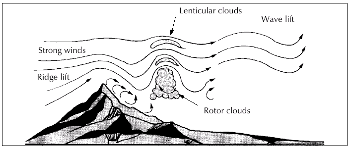
Fig. 83 Long lines of lenticular clouds perpendicular to the wind flow, which remain stationary, are the prime indication of the wave conditions.
Associated with wave are very strong lift and sink, and severe turbulence in the rotor areas which occur between each row of lenticulars. The rotor turbulence can be encountered at the altitudes microlights normally operate in, and has been responsible for inflight destruction of aircraft.
Generally speaking, the wind required for the wave system to form would normally preclude microlight operations. However, if the surface winds are not excessive but a wave system is present, expect higher upper winds and violent turbulence in the lee of the ranges.
In some parts of the country, wave formations are often enormous, with the wave systems extending many miles downwind and with lift and sink in regions sometimes reaching the 30,000ft mark! Microlights are not suited to tackling wave conditions. Sometimes, smaller localised wave systems can develop.
Wake Turbulence
The following has been reproduced from the February/March 1984 Flight Safety Magazine.
Although the discussion deals mainly with wake turbulence produced by aircraft of jet transport size, from a microlight pilot's point of view the wake from any other aircraft needs to be avoided.
Light wing loading, low speeds and often less than sharp control response (especially roll) make microlights more susceptible to wake turbulence.
Vortex Generation
Lift is generated by the creation of a pressure differential over the wing surface of an aircraft, the lower pressures being above the airfoil. This pressure difference induces a rolling motion in the airflow behind the aircraft, producing swirling air masses which trail downstream from the wing tips. As the rolling motion is completed, the wake develops into two counterrotating, cylindrical vortices, the characteristics of which vary according to conditions, aircraft configuration and changes of airspeed. They may be described as a pair of horizontal tornadoes trailing behind the wingtips.
Wake vortex strength is directly related to lift generated, size of the airfoil and angle of attack of the airfoil, and is general y inversely proportional to the airspeed of the generating aircraft. The greater the weight of the aircraft (fixed or rotor wing) the more intense will be the wake. The longer and broader the airfoil the greater the area affected. Tangential velocities of up to 85 metres per second (166 kts) within the vortex core have been recorded in trials conducted with Boeing 747 and 727 aircraft.
The danger to light aircraft from wake turbulence stems from the fact that this rate of roll easily exceeds their control capabilities, particularly when the affected aircraft has a shorter wingspan than that of the generating aircraft. As an indication of how powerful wake vortices can be, the pilot of a Beech Bonanza approaching an airport in the US planned to pass above the altitude of an airliner that was on base leg for landing. At 1170ft AGL and indicating 160 MPH, the pilot heard a loud bang and felt a jolt. The control wheel jerked aft and the aircraft abruptly entered what the pilot described as a wingslevel loop of some 35 seconds duration. After coming out of the upset manoeuvre he could not read his instruments because of severe vibration. After reducing power and airspeed, the vibration ceased and he completed a safe landing. Structural deformation was discovered on the right hand stabiliser.
The degree of danger associated with wake turbulence diminishes in direct proportion to the distance and time interval between the aircraft involved, and the height above ground at which it occurs. These factors directly affect the chances of recovery from an upset. Wake urbulence strength is likely to be at its peak when the generating aircraft is large, clean (flaps and landing gear retracted), and flying slowly, which suggests that a large aircraft in the holding configuration presents the greatest threat of wake turbulence.
Vortices generated near ground level typically last between one and two minutes, while those generated at higher altitudes can last as long as five minutes, leaving a trail of turbulent air several miles long.
Vortex Behaviour
The movement of these areas of violently disturbed air conforms to certain predictable patterns in most instances, enabling pilots to visualise the wake location and thus avoid the vortex core.
Vortices generated at altitude sink at a rate of 400-500 feet per minute initially, then gradually stabilise 900-1,000ft below the flight path of the generating aircraft. Eventually the vortices break up, the process being hastened by any atmospheric turbulence.
The cardinal rule for avoiding a wake turbulence encounter is to keep clear of the area behind and below a generating aircraft ahead, whether taking off, landing or flying en route. All precautionary techniques are based on that principle.
Pilots should be particularly alert to the possibility of wake turbulence in calm conditions and in situations where the vortices could:
- Remain in the touch down area.
- Drift across from an aircraft operating on a nearby runway.
- Sink into the flight path of an aircraft flying at a lower altitude.
Other rules of thumb are:
- Be particularly cautious when a light quartering tail wind exists on approach and a larger aircraft has already landed.
- Use the full length of runway available to help to keep the climbout path above that of preceding aircraft.
- Be alert for wake turbulence when a preceding large aircraft has executed goround, or when your rotation point wil be further along the runway than that of a preceding large aircraft.
- If you are in doubt about the possible existence of wake turbulence, delay the takeoff or execute a goround
.
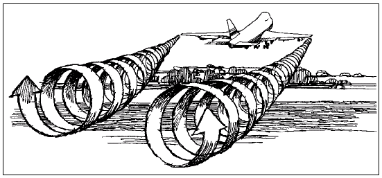
Fig. 84 Wake generated behind a Boeing 747 on takeoff.
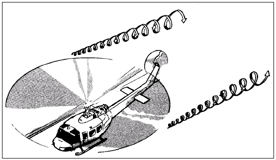
Fig. 85 Wake generated by a helicopter in flight is similar to that of a fixed wing aircraft.
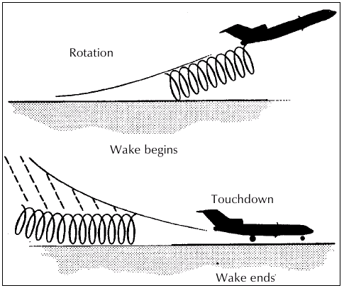
Fig. 86 On nosewheel aircraft wake vortices are generated at the point of rotation for takeoff .
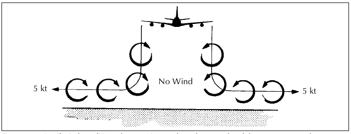
Fig. 87 In nil wind conditions these vortices settle to the ground and then move outwards at a speed of about 5 knots.
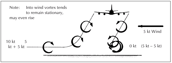
Fig. 88 If a light crosswind is present, it will arrest or impede the outward movement of the upwind vortex while assisting the movement of the downwind vortex.